Wednesday, February 12, 2020

Cloud vs. Cloud Native

Introduction

These days everyone is moving “On cloud”. Having many cloud vendors with lucrative offers of TCO reduction, does deploying your application in cloud makes you cloud-ready?

“Cloud Native” is more than just moving part or all of your applications to a cloud vendor. This requires a completely different approach towards application architecture, application development, team alignment, infrastructure etc. etc. Let’s take a deep dive to understand what actually “Cloud Native Architecture” means and why it is important.  

By definition: “Cloud Native” is an approach for architecture, development and deployment of applications; which takes the characteristics and nature of the cloud into account - resulting in processes and workflows that fully take advantage of the platform.

So what does fully taking advantage of the cloud means?


Cloud Brings Microservice

Traditional on-premise infrastructure used to be a centralized system. To all intents and purposes, everything was in one place. However, in cloud servers, databases etc. are distributed. In this context, if you simply migrate your existing application from traditional on-premise server to the cloud, it won’t give you much ROI from your migration. It will be simply as equal to as changing your hardware on-premise (or may be worse in sense they are no longer one centralized system any more).This is because applications those were hosted on on-premise servers were built as monoliths. Applications were including every feature and service that was meant to make them a single, big lump of code. Current day, with microservice architecture, applications are being built as a collection of distributed services, which compliments the distributed nature of the cloud perfectly. This approach gives individual microservices the advantage to automate in all possible ways to maximize the efficiency and minimize the cost & effort:

·        Auto Provisioning: Automatically provisioning environments as code
·        Auto Scaling: Tracking utilization of various modules/services within your application and scale up/down resources automatically whenever & wherever required
·        Auto Redundancy: Cloud Native applications are resilient to failure, by nature. In the event of a service degradation, application instances move to another server or data center automatically and seamlessly.

So, Cloud with microservices provide more granular means of deploying resources required for maintaining performance & reliability (SLA). While it’s possible to just migrate your existing monolith application with its legacy codebase to a cloud platform, however you won’t be able to get any of the benefits of being truly “Cloud Native”.


Microservices Brings Containers

The main driving factor for the rise of underlying container ecosystem (e.g. Docker, CoreOS rkt, Mesos, LXC etc.) is the microservices architecture. Managing your applications as a collection of individual (micro) services has implications on infrastructure. Since every service in a microservices application needs to be a self-contained unit, they need their own allocation of computing, memory, and network resources. From a cost and management point of view, it is not feasible to multiply 10 or 100 times the number of VMs to host individual (micro) services of your application as you move to the cloud. This is where containers come into the existence. Containers lightweight, standalone, executable package of software that includes everything (in right amount) needed to run an application: code, runtime, system tools, system libraries and settings. They make great alternative to VMs for packaging microservices, enabling the benefits mentioned above.


Container Brings Service Mesh Capabilities

With introduction of microservice and container; services have become more agile and location transparent. So the “Cloud Native” architecture demands more mesh or collaboration capabilities from services.

Let’s imagine that you are running an application that invokes other services or within your Cloud Native application different modules / (micro) services interacting with each other over a REST API or Thrift API. In order to make a request, your consumer needs to know the location of the provider service instance. In a traditional application running on a few hardware servers in a data center, the service locations are relatively static. For example, your code can read the network locations from a configuration file that is occasionally updated. In a modern, “Cloud Native” Microservice driven application, where main ideology is to run anywhere transparently, this is a much more difficult problem to solve. Because Service instances have dynamically assigned network locations. Moreover, the set of service instances changes dynamically for Auto Scaling, failures, and upgrades. Consequently, your client code needs to use a more elaborate service discovery mechanism.

This bring the considerations to re imagine the dynamic discovery patterns (e.g. Client‑Side Discovery Pattern, Server‑Side Discovery Pattern etc.), Service registry, Circuit breakers, API Gateway etc.

There are bunch of open source projects that help to design better mesh or collaboration capabilities for services. E.g. Zuul, Eureka, Hystrix, Ribbon, Gravitee etc.


Cloud, Microservice, Containers, Service Mesh together Brings “Cloud Native” Tools

The fundamental change in infrastructure with introduction of cloud demands a change in tools as well. Legacy tools those were built to manage tasks across a few hardware servers in a data center, can no longer sustain the complexity of microservices running in containers across the cloud. While cutting across a distributed containerized microservice based application, simple things like latency optimization, RCA of the backend, E2E monitoring etc can be complex. The resource consumption of each microservice needs to be metered to ensure degrading SLA for one service don’t affect others.

There are bunch of open source projects that help run microservice applications. E.g. Kubernetes, Containerd, Fluentd, Prometheus, Envoyproxy, CoreDNS, Jaegertracing, Vitess etc.


Cloud, Microservice & Containers together Brings Devops

Traditional application require different teams for each stage of an application’s lifecycle e.g. Development, DBA, QA, System Admin, RM, PM etc. with each team having their own goals and priorities. Team’s priorities often clash, and it takes a toll on the overall application delivery & maintenance.

With introduction of cloud, microservices & containers, team structures can be realigned to reflect the change in application development, deployment & maintenance architecture.

Modern software delivery teams are small and cross-functional fitting perfectly into “two pizza rule”. Teams are structured and organized by the services they support. This keeps team’s agile, improving collaboration and decision-making. It also eliminates the accountability issues, whereby teams can renounce responsibility for a feature after it is moves on from their team, but before it is released.


Cloud Native Release

With the right architecture to build applications, the right tools to manage them, and the right team structure to bring it all together, the comprehensive effect is that Cloud Native Applications has become more agile & frequent in terms of their releases. In essence, there is no longer any major releases, since every release affects a single (micro) service, or a couple of (micro) services at most. Due to the limited scope for every release, the find & fix are easy now. With capability automatic rollback tools, it is much easier to revert to the previous stable release when a new release fails.

Autonomous independent teams can ship updates to the services they own without any conflict with other teams. With multiple teams simultaneously releasing updates to services frequently, the pace of deployment is sky high. Netflix engineers deploy code thousands of times per day.

The biggest advantage of a “Cloud Native” architecture is that it takes a concept to rollout (Time to Market) in the quickest possible time.


Conclusion

“Cloud Native” architecture is more than just migrating your existing application to any cloud instance. It goes way further to change the way application is architected, planned & provisioned into the infrastructure, effectively monitored and maintained.

You can start your modernization journey (if not yet started) with an application modernization assessment and then a single pilot project, allowing you to become familiar with this approach before growing your cloud adoption further over time.

Next time you hear someone talking about cloud, stop and think if it really mean “Cloud Native”.

Wednesday, August 30, 2017

Integrating business process automation engine with existing TIBCO EMS

In todays world of business process automation, many of us are using WebSphere Process Server as their Integrating business process automation engine. However the need arises to integrate with existing messaging infrastructure. Today we will see, how to integrate TIBCO Enterprise Message Service, with WebSphere Process Server.

WebSphere Process Server is a business process integration server that helps you solve complex business flows and a platform that you can use to connect to various technologies. Businesses seeking to use WebSphere Process Server to implement these complex business processes have to be connected to other back-end or front-end systems in order for these business processes to work properly. TIBCO Enterprise Message Service (EMS) is a common messaging resource used by businesses. Since EMS supports JMS, we will use the JMS support of WebSphere Process Server to bind to EMS.


Presuming our enviroment running the following versions of WID, EMS & WPS on Windows 32 bit:

WebSphere Integration Developer V6.0.x.
TIBCO EMS server.
WebSphere Process Server V6

Steps to follow:

A. Configuring EMS and WebSphere Process Server
A.1. Start the EMS server
A.2. Create the EMS administered objects
A.3. Configure WebSphere Process Server for the EMS
A.4. Add EMS as a JMS provider to WebSphere Process Server
A.5. Configure the JNDI bindings for the EMS Connection Factories for WebSphere Application Server
A.6. Configure the JNDI bindings for TIBCO Enterprise Message Service Destinations for WebSphere Application Server
A.7. Create the Listener Ports for EMS
A.8. Create the Connection Factories and Destinations for WebSphere Default Messaging
B. Creating a business process
C. Creating the TIBCO EMS Message Producer
D. Configuring the Resource references
E. Creating the TIBCO Message Receiver Message Drive Bean (MDB)
F. Building and running the sample


A. Configuring EMS and WebSphere Process Server


A.1. Start the EMS server

Install the EMS
Choose Start => All Programs => TIBCO => TIBCO EMS Evaluation Version => Start EMS Server
Choose Start => All Programs => TIBCO => TIBCO EMS Evaluation Version => Start EMS Server Administration Tool
Type in connect and press Enter
Press Enter for login and password (no security configured), and you will see a message saying connected to tcp://localhost:7222 and the same as the command prompt

A.2. Create the EMS administered objects

Start the admin tool and enter the following commands:
Create factory sample.XAQCF xaqueue.
Create queue sample.Q1.

A.3. Configure WebSphere Process Server for the EMS JNDI provider

Create a text file called jndi.properties in the directory: \AppServer\lib\ext
Add the following line into the file:
java.naming.factory.url.pkgs=com.tibco.tibjms.naming
Save the jndi.propertiesfile

A.4. Add EMS as a JMS provider to WebSphere Process Server

Start Process Server
Start the Process Server Administrative Console
Expand Resources and choose Generic JMS Providers
Click New
Enter the following values for the given properties:
Name= TIBCO
Description= TIBCO Enterprise Message Service
Classpath= (location of tibjms.jar)
External Initial Context Factory= com.tibco.tibjms.naming.TibjmsInitialContextFactory
External Provider URL= tibjmsnaming://localhost:7222
Click OK
Click Save on the task bar at the top of the console window
stop, and restart WebSphere Application Server

A.5. Configure the JNDI bindings for the EMS Connection Factories for WebSphere Application Server

Expand Resources and choose Generic JMS Providers
In the content pane, choose TIBCO
Scroll down and choose JMS Connection Factories
Click New
Enter the following values for the given properties:
Name= TIBCOConnectionFactory
Type= QUEUE
JNDI Name= jms/ConnectionFactory
Description= Sample Queue ConnectionFactory
External JNDI Name= sample.XAQCF
Click OK
Click Save on the task bar of the Administrative Console (and Save again to confirm)
stop, and restart the WebSphere Application Server

A.6. Configure the JNDI bindings for TIBCO Enterprise Message Service destinations for the WebSphere Application Server

Expand Resources and choose Generic JMS Providers
In the content pane, choose TIBCO
Scroll down and choose JMS Destinations
Click New
Enter the following values for the given properties:
Name= Q1
Type= QUEUE
JNDI Name= jms/Q1
Description= Sample Listen Queue
External JNDI Name= sample.Q1
Click OK
Click Save on the task bar of the Administrative Console (and Save again to confirm)
stop and restart the WebSphere Application Server

A.7. Create Listener Ports for EMS

Expand Servers and choose Application Servers
In the content pane, choose the name of the application server
In the Additional Properties Table, select Message Listener Service
In the content pane, select Listener Ports
In the content pane, click New
Enter the following values for the given listener port properties:
Name= TIBCOPtoPListenerPort
Initial State= Started
Description= Listener Port for TIBCO Point to Point
ConnectionFactory JNDI Name= jms/ConnectionFactory
Destination JNDI Name= jms/Q1
Click OK
Click Save on the task bar of the Administrative Console (and Save again to confirm)
stop and restart the application server to have the changes take effect


Verify that the new listener ports are in their proper initial state
expand Servers => Application Servers=> => Message Listener Service=> Listener Ports
TIBCO listener ports should have a solid green arrow, indicating as started


A.8. Create Connection Factories and Destinations for WebSphere Default Messaging

Create a Service Integration Bus
name= MyBus
Destination names= TIBCO_WPS_Queue
Create a JMS Queue Connection Factory
Name= MyQueueConnectionFactory
JNDI Name= jms/MyConnectionFactory
Bus= MyBus
Create JMS Connection Factory
Name= TibcoConnectionFactory
JNDI Name= jms/TibcoConnectionFactory
Bus= MyBus
Create a JMS Queue
Name= TIBCO_WPS_JMS_Queue
JNDI= Name jms/tibcowpsq
Queue Name= TIBCO_WPS_Queue
Bus= MyBus
Create a JMS Activation Spec
Name= TIBCO_WPS_AS
JNDI Name= eis/tibcowpsas
Destination Type= Queue
Destination JNDI name= jms/tibcowpsq
Bus= MyBus


To Be Continued  ...

(Sorry didn't get time to finish. But I promise to finish some day ;))
Note: For WPS & WID tutorial you may refer http://www.webagesolutions.com/knowledgebase/waskb/waskb019/

Tuesday, April 10, 2012

Using Hudson as CI tool on WLS

One of the key concept of Service Oriented Architechture is that services are no longer built to last, but rather built to change.

In software engineering, continuous integration (CI) implements continuous processes of applying quality control — small pieces of effort, applied frequently. Continuous integration aims to improve the quality of software, and to reduce the time taken to deliver it, by replacing the traditional practice of applying quality control after completing all development.

Now if we follow SOA principles, then the design and implementation should be optimized. However what SOA doesn't address is how we build, deploy, test and finally released that code into production.

This is where a CI tool (details of CI can be found here) comes very useful.

Hudson is such a continuous integration (CI) tool written in Java, which runs in a servlet container, such as Apache Tomcat or the WebLogic application server. It supports SCM tools including CVS, Subversion, Git and Clearcase and can execute Apache Ant and Apache Maven based projects, as well as arbitrary shell scripts and Windows batch commands.

In the following steps we will see how to configure Hudson on WebLogic (Due to Weblogic's class loading structure, if the hudson.war is directly deployed, the application will fail to startup. This is to because there are jar conflicts between Hudson and Weblogic. To get around the issue, we use the FilteringClassLoader mechanism so that specific hudson jars get priority in the classpath over Weblogic's jars).

Versions
-----------
Hudson: 2.2.0
WebLogic: 10.3.1 (11g R1)

Steps:
-----------
1> Downnload Hudson Binary (2.2.0) from here
2> Unzip downloaded hudson.zip
3> Go inside the unzipped location and make a .war file from the content (jar -cvf hudson.war .)
4> copy the hudson war to a directory (e.g. E:\installers\hudson) and create another folder (META-INF) in it.
5> add application.xml and weblogic-application.xml in the META-INF directory

application.xml
===============


weblogic-application.xml
========================


6> Repackage the complete content in hudson.ear and deply in WebLogic
7> Access the Hudson on http://<server_ip>:<port>/hudson

Monday, April 9, 2012

Enabling OSB to support X.509 token identity

In cryptography, X.509 is an ITU-T standard for a public key infrastructure (PKI) and Privilege Management Infrastructure (PMI). X.509 specifies, amongst other things, standard formats for public key certificates, certificate revocation lists, attribute certificates, and a certification path validation algorithm. Further detail is available here

With OSB supporting X.509 certificates, guarantees that the hosts with which OSB communicates with are the ones that it expects.

Adding X.509 Support to the WebLogic Default Identity Asserter

Since OSB uses the underlying framework that is supplied by WLS, by setting the default identity asserter within WLS to accept X.509 certificates, we can allow users and/or processes to present X.509 certificates to identify themselves. To do this, we need to access the WebLogic Server console and open the Security Realm -> Providers -> Authentication tab.


within the Default Identity Asserter, under the common tab, move the X.509 token type from the available list to the chosen list.


Then under the Provider Specific tab, check the use of the Default Name Mapper. This checks that the certificates mapped to the user has not expired.


Adding WebLogic PKI Credential Mapping Provider

A Credential Mapping provider allows WebLogic Server to log into a remote system on behalf of a subject that has already been authenticated. You must have one Credential Mapping provider in a security realm, and you can configure multiple Credential Mapping providers in a security realm. It is only one of the types of credential mapper that are available. For this example we will need to have a keystore available. To do this you might need to use the keytool command.

The basic steps to create a keystores (jks) using keytool can be referred in the jdk documents, for reference the following are four easily usable commands to create identity, trust stores along with a certificate (self signed)

keytool -genkey -alias test -keyalg RSA -keysize 1024 -dname "cn=L-0219016978.XXX.com,ou=Consulting,o=XXX" -keypass password -keystore identity.jks -storepass password
keytool -selfcert -v -alias test -keypass password -keystore identity.jks -storepass password -storetype JKS
keytool -export -v -alias test -file rootCA.der -keystore identity.jks -storepass password
keytool -import -v -trustcacerts -alias test -file rootCA.der -keystore trust.jks -storepass password

To configure a Credential Mapping Provider, we need to add a new provider in the security realm, under Providers -> Credential Mapping, by clicking “New”


Once, the PKI Credential Mapper is created, configure it as below.


The type of keystore will by JKS and the keystore filename/password will be the ones given while using keytool to create the keystore.

Configuring OSB Inbound WebServices


Within the web services security list, the default_x509_handler is the one that we need to change (to use the newly created keystore).


Nw we need to set up the Token Handler Property of UseX509ForIdentity to be true.


Configuring WebLogic for SSL

The next step is to configure WebLogic Server for SSL, using the same keystore.


Next step is to create an user that is contained within certificate from the keystore. After these dynamic changes, server need to be restarted

Once we complete the above mentioned steps, our OSB system is ready to suppot the X.509 token identity.

Further reference can be pointed to Oracle WebLogic Documentation:

http://docs.oracle.com/cd/E13222_01/wls/docs103/ConsoleHelp/taskhelp/webservices/webservicesecurity/CreateDefaultWSSConfig.html
http://docs.oracle.com/cd/E13222_01/wls/docs103/ConsoleHelp/taskhelp/webservices/webservicesecurity/UseX509ForIdentity.html

Tuesday, October 11, 2011

Enterprise Integration using Web Services

From last couple of days, while working on an integration activity I was going through some of the Enterprise Integration Patters (EIP) and was also having couple of round of discussion with my clients. During this period of time I got the idea of writing some notes on this topic so that if anyone is already working on this can get some help from the post (read "can help me by giving me back some new ideas").

EI has numerous patterns and we will be looking most importantly the webservice based models in this post.

There are two principal architectures for Web service interfaces

A> Synchronous Web services
B> Asynchronous Web services


These two architectures are distinguished by their way of request/response handling pattern. With synchronous services, clients invoke a request on a service and then suspend activity to wait for a response. With asynchronous services, clients initiate a request to a service and then resume their processing without waiting for a response. The service handles the client request and returns a response when available later. Upon availability of the response, the client retrieves the response for further processing.

However a Web service may combine synchronous and asynchronous architecture depending upon the types of work, the service performs and the available technologies.

A> Synchronous Web Services

Synchronous services are characterized by the client invoking a service and then waiting for a response to the request. Since the client suspends its own processing after making request, this approach is best when the service can process the request in a small amount of time. Synchronous services are also best when applications require a more immediate response to a request. Web services that rely on synchronous communication are usually RPC-oriented. Generally, consider using an RPC-oriented approach for synchronous Web services.

A credit card service, used in an e-commerce application, is a good example of a synchronous service. Typically, a client (the e-commerce application) invokes the credit card service with the credit card details and then waits for the approval or denial of the credit card transaction. The client cannot continue its processing until the transaction completes, and obtaining credit approval is a prerequisite to completing the transaction.

A stock quote Web service is another example of a synchronous service. A client invokes the quote service with a particular stock symbol and waits for the stock price response.


Pic: synchronous webservice model


Synchronous Web service mostly leverages the JAX-RPC servlet endpoint. Client makes the request to the servlet endpoint and then the servlet delegates the request to the service's appropriate business logic, which may reside in the service's Web tier or EJB tier. The service's business logic processes the request (It may access the business data through a persistence mechanism, if required) and When it completes its processing, formulates a response which is then returned to the client through the JAX-RPC servlet endpoint.


Pic: Synchronous webservice with JAX-RPC


A synchronous architecture like this also has the facility to expose a Web service interface to an existing J2EE application that may already have a browser/wireless/rich client interface.

B> Asynchronous Web Services

With asynchronous services, the client generates the request but doesn't wait for the response. Often, with these services, the client does not want to wait for the response because it may take a significant amount of time for the service to process the request and the nenxt operation is not directly dependent on the response (unlike the credit card response for the e-commerce application during check out).

Generally, an asynchronous class of services is used for document-oriented approaches.

A travel desk service is a good example of a document-oriented service that might get benefitted by using asynchronous communication, where the client sends a document to the travel service (may be for requesting arrangements for a particular trip or reimbursement for a trip). Based on the document's content and/or the workflow defined within the business logic of the service, it starts processing. Since the travel service might perform time-consuming steps in its normal workflow, the client cannot afford to pause and wait for these steps to complete.

So far so good. The synchronous calls are easy enough, since we do not need to think about a way out of delayed response tracking. Now in case of Asynchronous calls the service may make the result to the client's request, available in one of two ways:

1> the client that invoked the service periodically checks the status of the request using the ID that was provided at the time the request was submitted. (This is also known as polling.)
2> If the client itself is a Web service peer, the service calls back the client's service with the result.


While designing the architecture of asynchronous webservice based integration, we can think of multiple design patterns. The above architecture shows one of the recommended approaches to achieve asynchronous communication. In this architecture, the client sends a request to the JAX-RPC servlet endpoint on the web container. The servlet endpoint delegates the client's request to the appropriate business logic of the service. It does so by sending the request as a JMS message to a designated queue or topic. The JMS layer (along with the message-driven beans) makes asynchronous communication possible.

The above architecture shows the scenario in case the client itself is a Web service peer. The client application (which could be a direct client or another web container) generates a request and sends it via JMS to the Processing Center (Service A). "Service A" has a Web service invoker that sends the request to the destination application's Web service endpoint (Service B). The endpoint receives the request and acknowledges the receipt by sending an ID back to the service invoker. Later, when the supplier application fulfills the request, its Web service invoker sends the result to "service A" endpoint.


As I mentioned earlier, there could be numerous approaches to achieve this pattern and the above mentioned are only two of them. In case you are interested to add anything, please feel free to write note on the post.

Sunday, September 4, 2011

SOA concept and role of an ESB in it

This posts is influenced by my one of my recent discussion about Service Oriented IT trends with couple of my friends. Since SOA being a recent buzz word and with couple of very good implementation of it present in current market from some of the software giants, it has become absolute necessity to understand the concept first.

Service-Oriented Architecture

Service-Oriented Architecture (SOA) has emerged as the leading IT agenda for infrastructure reformation, to optimize service delivery and ensure efficient business process management. Part of the paradigm shift of SOA are fundamental changes in the way IT infrastructure is designed—moving away from an application infrastructure to a converged service infrastructure. Service-Oriented Architecture enables discrete functions contained in enterprise applications to be organized as layers of interoperable, standards-based shared “services” that can be combined and reused in composite applications and processes.

In addition, this architectural approach also allows the incorporation of services offered by external service providers into the enterprise IT architecture. As a result, enterprises are able to unlock key business information in disparate silos, in a cost-effective manner. By organizing enterprise IT around services instead of around applications, SOA helps companies achieve faster time-to-service and respond more flexibly to fast-paced changes in business requirements.

In recent years, many enterprises have evolved from exploring pilot projects using ad-hoc adoption of SOA and expanded to a defined repeatable approach for optimized enterprise-wide SOA deployments. All layers of an IT SOA architecture have become service-enabled and comprise of presentation services, business processes, business services, data services, and shared services.


Fig: SOA Conceptual Architecture


Service Mediation Challenges

A major challenge for SOA initiatives is attributed to the inherently heterogeneous multi-vendor IT landscape in many enterprises, and the resultant individual silos of business information. Rather than incur the cost and complexity of replacing disparate components of legacy infrastructure, enterprises often choose to extend existing business applications as services for use in other business processes and applications.

The influx of Web service interfaces to functionality within existing packaged applications, often introduces services that do not adhere to established service and compliance guidelines. This is especially true if the services are published from core enterprise systems such as CRMs, Data Warehouses, and ERPs.

In the absence of robust and comprehensive service infrastructure solutions, developers have used a variety of “middleware” technologies to support program-to-program communication, such as object request brokers (ORBs), message-oriented middleware (MOM), remote procedure calls (RPC). More recently, IT infrastructure developers hard-coded complex integration logic as point-to-point connections to web services, in order to integrate disparate applications and processes. This inevitably resulted in complex service sprawls within enterprise IT environments. The following figure illustrates a typical static service integration scenario.


Fig: Service Sprawl Challenge


The following are other service related challenges attributed to heterogeneous IT architectures:


  • Tightly-coupled business services integration due to complex and rigid hard-wired connections

  • Difficulty managing deployed services due to disparate protocols and applications involved

  • High total cost of ownership for the enterprise

  • Impaired ability to reuse services

  • Inherent replication of transport, transformation, security, and routing details

  • Exponential redevelopment and redeployment efforts when service end-point interfaces change

  • Inevitable service disruption that significantly impact service consumers
Enterprise architects and web service modelers with goals to streamline IT infrastructure now require enterprise service capabilities that address the following IT needs:


  • Simplify access and updates to data residing in different sources

  • Reuse services developed across the enterprise and effectively manage their lifecycle

  • Provide dynamic configuration of complex integration logic and message routing behavior

  • Enable run-time configuration capabilities into the service infrastructure

  • Ensure consistent use of the enterprise services

  • Ensure enterprise services are secure and comply with IT policies

  • Monitor and audit service usage and manage system outages
Composite Applications and Service Layering

In an SOA initiative, composition is an integral part of achieving business flexibility through the ability to leverage existing assets in higher-order functions.Within a mature SOA environment, complete business applications are composed using existing services to quickly meet the business needs. Flexibility in the service provisioning process, is achieved by avoiding coding logic in service implementations.

Many organizations develop services at very granular levels and the proliferation of many small specific services are difficult to compose into broader logical services. Layering of Services is as a way of breaking out of the limitations of monolithic applications and shortening development, release and test cycles. By defining a layered approach to service definition and construction, the service infrastructure team can achieve the right mix of granular and course-grained services required to meet their current and future business demands. Service Layers typically comprise of the following services:


  • Physical Services: that may represent functions that retrieve data in its raw form

  • Canonical Services: that may define a standard view of information for the organization, leveraging industry-standard formats and supporting a very wide data footprint

  • Logical Services: that provide a more client-specific granular view of information, generated at compile time using highly-optimized queries

  • Application Services: that are consumed directly by applications in a line-of-business dependent fashion and may be exposed through presentation services
Service Bus Component of SOA

The core of SOA success depends on an Enterprise Service Bus (ESB) that supports dynamic synergy and alignment of business process interactions, continual evolution of existing services and rapid addition of new ones. To realize the benefits of SOA, it is imperative that IT organizations include a robust and intelligent service intermediary that provides a layer of abstraction to mask the complexities of service integration in heterogeneous IT environments, typical in today’s enterprises. While an intermediary layer of abstraction previously implied a platform for customizing enterprise applications, today it implies toolkits for service customization and scalable infrastructures that support loosely coupled service interactions with a focus on service mediation.


Fig: Enterprise Service Bus

ESBs have been instrumental in the evolution of integrated middleware infrastructure technology by combining features from previous technologies with new services, such as message validation, transformation, content-based routing, security and load balancing. ESBs use industry standards for most of the services they provide, thus facilitating cross-platform interoperability and becoming the logical choice for companies looking to implement SOA.

An ESB provides an efficient way to build and deploy enterprise SOA. ESB is a concept that has gained the attention of architects and developers, as it provides an effective approach to solving common SOA hurdles associated with service orchestration, application data synchronization, and business activity monitoring. In its most basic form, an ESB offers the following key features:


  • Web services: support for SOAP, WSDL and UDDI, as well as emerging standards such as WS-Reliable Messaging and WS-Security

  • Messaging: asynchronous store-and-forward delivery with multiple qualities of service

  • Data transformation: XML to XML

  • Content-based routing: publish and subscribe routing across multiple types of sources and destinations

  • Platform-neutral: connect to any technology in the enterprise, e.g. Java, .Net, mainframes, and databases


Fig: ESB Architecture


A robust SOA suite offers:


  • Adapters, to enable connectivity into packaged and custom enterprise applications, as well as leading technologies.

  • Distributed query engine, for easily enabling the creation of data services out of heterogeneous data sources

  • Service orchestration engine, for both long-running (stateful) and short-running (stateless) processes

  • Application development tools, to enable the rapid creation of user-facing applications

  • Presentation services, to enable the creation of personalized portals that aggregate services from multiple sources
Using ESBs offers greater flexibility for enterprises to connect heterogeneous resources, by eliminating the need for brittle high-maintenance point-to-point connections. Adding an ESB intermediary between service consumers and service providers, shields them from the implementation details of underlying service end-point interfaces, reducing or eliminating the redevelopment and redeployment impacts at the service-consumer level.

Best in class enterprises have achieved SOA success by harnessing high-speed enterprise-ready ESB intermediaries that strategically integrate service mediation capabilities and business process management functionality. Recognizing the significance of operational service management as a critical SOA success factor, they have implemented solutions that provide enterprise-class service scalability, reliability, customization and security. By adopting such solutions built specifically for management and governance of an SOA service lifecycle, these enterprises have obtained the following business benefits:


  • Minimized costs by accelerating SOA deployment initiatives

  • Ensured customer satisfaction by assurance of continuous service availability

  • Insulated service consumers to changes in service infrastructure by virtualizing service end points

  • Maximized ROI by leveraging shared services infrastructure and using consistent modeling methodologies

  • Reduced integration burden by simplifying service interactions

  • Improved effectiveness of SOA initiatives through accurate run-time governance of shared services

  • Justification of SOA spending by inventory and tracking of run-time services

  • Accurate cost benefit decisions by measuring the benefit or cost avoidance obtained through SOA

Fig: Enterprise Integration for SOA


Hope this will help to understand the concept and drive of the SOA initiative. My many thanks to one of the leading SOA implementation vendor document to put up this post together.

Tuesday, September 28, 2010

Browsing your destinations using Hermes

When we talk about the Messaging Middleware, administering the destinations is a must-have feature. A lot of queries come 'How to browse, search, copy, and delete messages from destinations'...

The WebLogic Server Administration Console comes with the feature to monitor and view JMS messages from WebLogic 9.x onwards. However it is a web-based (console) tool that is optimized for configuration, not monitoring and development testing. It can not do some advanced JMS activities like copy messages from one queue to another very easily. HermesJMS is an extensible console that helps you interact with JMS providers making it easy to browse or search queues and topics, copy messages around and delete them. It fully integrates with JNDI letting you discover administered objects stored, create JMS sessions from the connection factories and use any destinations found. Many providers include a plug-in that uses the native API to do non-JMS things like getting queue depths (and other statistics) or finding queue and topic names.

This little but powerful tool works with many of the popular JMS providers such as WebLogic JMS, Tibco EMS, JBoss MQ, Sonic MQ, WebSphere MQ, OpenJMS, SAP etc.

In this post we will see how to get Hermes installed and configured for use with WebLogic JMS.

1> Download the installer from HERE
2> Run “java –jar hermes-installer-1.13.jar” (at the time of writing this post the version available is 1.13, you may have a different JAR file name) in the directory where you have placed the installer jar.
3> Edit the /bin/hermes.bat or hermes.sh and set JAVA_HOME (if you do not have it set at the System level)
4> Create JMS module > Connection Factory > Destination (If you have an already existing Destination on WLS, then you may skip this point).
5> Launch Hermes by calling the hermes.bat
6> Right click on “sessions” and select “new -> New session”
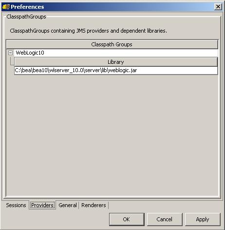
7> Go to the “providers” tab at the bottom and add a “group” called “weblogic10” and a “library” specifying your path to weblogic.jar. Select “Don’t Scan” when prompted. (I am using WLS 10.0 GA for this posting)


8> Save the configuration.
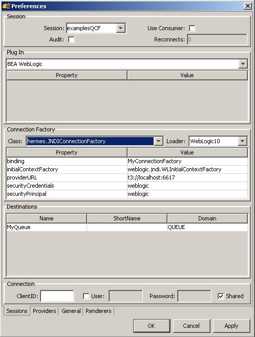
9> Click on the “Sessions” tab. Enter a name for the session (in this case “examplesQCF”). Select “BEA WebLogic” for the “Plug In” section from the dropdown. In the “Connection Factory”, select “weblogic10” for the loader. For the properties values refer the below image (binding, URL and credentials would be specific to your WLS settings).


10> Now right click on the newly created “examplesQCF” session and select Discover. It would list all the available destinations under the examplesQCF session.


11> Now right click on a single entry under the Session and select “Browse”, you should be able to see the contents of the queue.


If you are able to see something very similar like the snapshot above, that mean you have configured the Hermes properly.

Tuesday, July 27, 2010

What is a connector (resource adapter)?

Connectors as the name specifies, are nothing but the way of connecting to different components of an enterprise infrastructure more like an USB (plug and play) components. And the specification it adheares to is the Java Connector Architecture (JCA).
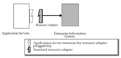
The J2EE Connector Architecture defines standard Java interfaces for simplifying the integration of enterprise applications with J2EE-based Java applications. With these interfaces, Java developers can access existing databases, ERP applications and legacy systems. The connector, also known as a "resource adapter," appears as a component library that the developer can access via Java programming language.

The JCA has two basic components, the Common Client Interface (CCI) and a set of system-specific services. An adapter developer provides an interface to CCI along with its side of the system contracts specified as part of the connector architecture. The application server vendor implements its side of the system contracts as part of its base J2EE platform.

CCI is a programming interface that application developers and client programs can use to connect and access back-end systems. It is a low-level API and similar to JDBC. Unlike JDBC, however, CCI can work with nonrelational systems. CCI manages the flow of data between the application and the back-end system and does not have any visibility into what the container and the application server are doing. Although it is possible for application developers to call the CCI directly, in most cases, an application developer will write to an abstraction layer, provided by the connector provider or enterprise application integration (EAI) framework vendor, to simplify the development process.

On the platform side, JCA defines a set of service contracts that a connector developer can expect will be available to the adapter at application runtime. Like CCI, the specification defines what services need to be present, and again, it is up to the application server vendor to provide the actual implementation.

To enable seamless integration with an application server, a resource adapter must abide by guidelines, known as system-level contracts. These contracts specify how a system external to the J2EE platform can integrate with it by supporting basic functions that are handled by the J2EE container. There are three major categories of these functions:

Connection management
The connection management contract allows applications to connect to an EIS. It also enables the application server to utilize pooling.

Transaction management
The transaction management contact allows an application to manage and perform transactional access across one to many EIS resource managers.

Security
The security contract provides support for secure access to the EIS.

How to build your own adapter

In this post we will try to demonstrate how to implement a JCA adapter - a set of classes with which a J2EE application server targets a particular enterprise system. A JCA adapter functions similarly to how a JDBC driver connects to databases. Developing a full-featured JCA adapter is a complex task. However, by the end, you will understand a basic JCA adapter's construction, and grasp the effort required to build your own.

This sample adapter will actually connect to an enterprise system. It only implements (for demonstration purpose) the interfaces required to deploy an adapter and look up a connection. (And we are not going to use Common Client Interfaces [CCI] either).

The adapter includes two class categories:

Managed classes: The application server calls managed classes to perform the connection management, required only if the application server is managing the connection through a connection pool.

Physical connection classes: These classes can get called by the managed classes to establish the connection to an EIS (enterprise information systems).

MyManagedConnectionFactory

With the MyManagedConnectionFactory class, which implements the ManagedConnectionFacytory interface, you create the MyConnectionFactory and MyManagedConnection classes. The MyManagedConnectionFactory class is the main entry point for the application server to invoke the adapter:

package org.acme.jca;
import java.io.PrintWriter;
import java.io.Serializable;
import java.sql.DriverManager;
import java.util.Iterator;
import java.util.Set;
import javax.resource.ResourceException;
import javax.resource.spi.*;
import javax.security.auth.Subject;
public class MyManagedConnectionFactory
implements ManagedConnectionFactory, Serializable
{
public MyManagedConnectionFactory() {
System.out.println("In MyManagedConnectionFactory.constructor");
}
public Object createConnectionFactory(ConnectionManager cxManager) throws ResourceException {
System.out.println("In MyManagedConnectionFactory.createConnectionFactory,1");
return new MyDataSource(this, cxManager);
}
public Object createConnectionFactory() throws ResourceException {
System.out.println("In MyManagedConnectionFactory.createManagedFactory,2");
return new MyDataSource(this, null);
}
public ManagedConnection createManagedConnection(Subject subject, ConnectionRequestInfo info) {
System.out.println("In MyManagedConnectionFactory.createManagedConnection");
return new MyManagedConnection(this, "test");
}
public ManagedConnection matchManagedConnections(Set connectionSet, Subject subject, ConnectionRequestInfo info)
throws ResourceException
{
System.out.println("In MyManagedConnectionFactory.matchManagedConnections");
return null;
}
public void setLogWriter(PrintWriter out) throws ResourceException {
System.out.println("In MyManagedConnectionFactory.setLogWriter");
}
public PrintWriter getLogWriter() throws ResourceException {
System.out.println("In MyManagedConnectionFactory.getLogWriter");
return DriverManager.getLogWriter();
}
public boolean equals(Object obj) {
if(obj == null)
return false;
if(obj instanceof MyManagedConnectionFactory)
{
int hash1 = ((MyManagedConnectionFactory)obj).hashCode();
int hash2 = hashCode();
return hash1 == hash2;
}
else
{
return false;
}
}
public int hashCode()
{
return 1;
}
}

MyManagedConnection

The MyManagedConnection class implements the ManagedConnection interface. MyManagedConnection encapsulates the adapter's physical connection, in this case the MyConnection class:

package org.acme.jca;
import java.io.PrintWriter;
import java.sql.Connection;
import java.sql.SQLException;
import java.util.*;
import javax.resource.NotSupportedException;
import javax.resource.ResourceException;
import javax.resource.spi.*;
import javax.security.auth.Subject;
import javax.transaction.xa.XAResource;
public class MyManagedConnection
implements ManagedConnection
{
private MyConnectionEventListener myListener;
private String user;
private ManagedConnectionFactory mcf;
private PrintWriter logWriter;
private boolean destroyed;
private Set connectionSet;
MyManagedConnection(ManagedConnectionFactory mcf, String user)
{
System.out.println("In MyManagedConnection");
this.mcf = mcf;
this.user = user;
connectionSet = new HashSet();
myListener = new MyConnectionEventListener(this);
}
private void throwResourceException(SQLException ex)
throws ResourceException
{
ResourceException re = new ResourceException("SQLException: " +
ex.getMessage());
re.setLinkedException(ex);
throw re;
}
public Object getConnection(Subject subject, ConnectionRequestInfo
connectionRequestInfo)
throws ResourceException
{
System.out.println("In MyManagedConnection.getConnection");
MyConnection myCon = new MyConnection(this);
addMyConnection(myCon);
return myCon;
}
public void destroy()
{
System.out.println("In MyManagedConnection.destroy");
destroyed = true;
}
public void cleanup()
{
System.out.println("In MyManagedConnection.cleanup");
}
public void associateConnection(Object connection)
{
System.out.println("In MyManagedConnection.associateConnection");
}
public void addConnectionEventListener(ConnectionEventListener listener)
{
System.out.println("In MyManagedConnection.addConnectionEventListener");
myListener.addConnectorListener(listener);
}
public void removeConnectionEventListener(ConnectionEventListener listener)
{
System.out.println("In MyManagedConnection.removeConnectionEventListener");
myListener.removeConnectorListener(listener);
}
public XAResource getXAResource()
throws ResourceException
{
System.out.println("In MyManagedConnection.getXAResource");
return null;
}
public LocalTransaction getLocalTransaction()
{
System.out.println("In MyManagedConnection.getLocalTransaction");
return null;
}
public ManagedConnectionMetaData getMetaData()
throws ResourceException
{
System.out.println("In MyManagedConnection.getMetaData");
return new MyConnectionMetaData(this);
}
public void setLogWriter(PrintWriter out)
throws ResourceException
{
System.out.println("In MyManagedConnection.setLogWriter");
logWriter = out;
}
public PrintWriter getLogWriter()
throws ResourceException
{
System.out.println("In MyManagedConnection.getLogWriter");
return logWriter;
}
Connection getMyConnection()
throws ResourceException
{
System.out.println("In MyManagedConnection.getMyConnection");
return null;
}
boolean isDestroyed()
{
System.out.println("In MyManagedConnection.isDestroyed");
return destroyed;
}
String getUserName()
{
System.out.println("In MyManagedConnection.getUserName");
return user;
}
void sendEvent(int eventType, Exception ex)
{
System.out.println("In MyManagedConnection.sendEvent,1");
myListener.sendEvent(eventType, ex, null);
}
void sendEvent(int eventType, Exception ex, Object connectionHandle)
{
System.out.println("In MyManagedConnection.sendEvent,2 ");
myListener.sendEvent(eventType, ex, connectionHandle);
}
void removeMyConnection(MyConnection myCon)
{
System.out.println("In MyManagedConnection.removeMyConnection");
connectionSet.remove(myCon);
}
void addMyConnection(MyConnection myCon)
{
System.out.println("In MyManagedConnection.addMyConnection");
connectionSet.add(myCon);
}
ManagedConnectionFactory getManagedConnectionFactory()
{
System.out.println("In MyManagedConnection.getManagedConnectionFactory");
return mcf;
}
}

MyConnectionEventListener

For its part, the MyConnectionEventListener class allows the application server to register callbacks for the adapter. The application server can then perform operations, connection-pool maintenance, for example, based on the connection state:

package org.acme.jca;
import java.util.Vector;
import javax.resource.spi.ConnectionEvent;
import javax.resource.spi.ConnectionEventListener;
import javax.resource.spi.ManagedConnection;
public class MyConnectionEventListener
implements javax.sql.ConnectionEventListener
{
private Vector listeners;
private ManagedConnection mcon;
public MyConnectionEventListener(ManagedConnection mcon)
{
System.out.println("In MyConnectionEventListener");
this.mcon = mcon;
}
public void sendEvent(int eventType, Exception ex, Object connectionHandle)
{
System.out.println("In MyConnectionEventListener.sendEvent");
}
public void addConnectorListener(ConnectionEventListener l)
{
System.out.println("In MyConnectionEventListener.addConnectorListener");
}
public void removeConnectorListener(ConnectionEventListener l)
{
System.out.println("In MyConnectionEventListener.removeConnectorListener");
}
public void connectionClosed(javax.sql.ConnectionEvent connectionevent)
{
System.out.println("In MyConnectionEventListener.connectorClosed");
}
public void connectionErrorOccurred(javax.sql.ConnectionEvent event)
{
System.out.println("In MyConnectionEventListener.connectorErrorOccurred");
}
}

MyConnectionMetaData

The MyConnectionMetaData class provides meta information -- product name, the maximum number of connections allowed, and so on -- regarding the managed connection and the underlying physical connection class:

package org.acme.jca;
import javax.resource.ResourceException;
import javax.resource.spi.*;
public class MyConnectionMetaData
implements ManagedConnectionMetaData
{
private MyManagedConnection mc;
public MyConnectionMetaData(MyManagedConnection mc)
{
System.out.println("In MyConnectionMetaData.constructor");
this.mc = mc;
}
public String getEISProductName()
throws ResourceException
{
System.out.println("In MyConnectionMetaData.getEISProductName");
return "myJCA";
}
public String getEISProductVersion()
throws ResourceException
{
System.out.println("In MyConnectionMetaData.getEISProductVersion");
return "1.0";
}
public int getMaxConnections()
throws ResourceException
{
System.out.println("In MyConnectionMetaData.getMaxConnections");
return 5;
}
public String getUserName()
throws ResourceException
{
return mc.getUserName();
}
}

MyConnection

The MyConnection class, which represents the underlying physical connection to the EIS. MyConnection is one of the few classes that does not implement an interface in the JCA specification. The implementation below is simplistic, but a working implementation might contain connectivity code using sockets, as well as other functionality:

package org.acme.jca;
public class MyConnection
{
private MyManagedConnection mc;
public MyConnection(MyManagedConnection mc)
{
System.out.println("In MyConnection");
this.mc = mc;
}
}

MyConnectionRequestInfo

The MyConnectionRequestInfo class contains the data (such as the user name, password, and other information) necessary to establish a connection:

package org.acme.jca;
import javax.resource.spi.ConnectionRequestInfo;
public class MyConnectionRequestInfo
implements ConnectionRequestInfo
{
private String user;
private String password;
public MyConnectionRequestInfo(String user, String password)
{
System.out.println("In MyConnectionRequestInfo");
this.user = user;
this.password = password;
}
public String getUser()
{
System.out.println("In MyConnectionRequestInfo.getUser");
return user;
}
public String getPassword()
{
System.out.println("In MyConnectionRequestInfo.getPassword");
return password;
}
public boolean equals(Object obj)
{
System.out.println("In MyConnectionRequestInfo.equals");
if(obj == null)
return false;
if(obj instanceof MyConnectionRequestInfo)
{
MyConnectionRequestInfo other = (MyConnectionRequestInfo)obj;
return isEqual(user, other.user) && isEqual(password, other.password);
} else
{
return false;
}
}
public int hashCode()
{
System.out.println("In MyConnectionRequestInfo.hashCode");
String result = "" + user + password;
return result.hashCode();
}
private boolean isEqual(Object o1, Object o2)
{
System.out.println("In MyConnectionRequestInfo.isEqual");
if(o1 == null)
return o2 == null;
else
return o1.equals(o2);
}
}

MyDataSource

The MyDataSource class serves as a connection factory for the underlying connections. Because the sample adapter does not implement the CCI interfaces, it implements the DataSource interface in the javax.sql package:

package org.acme.jca;
import java.io.PrintWriter;
import java.io.Serializable;
import java.sql.*;
import javax.naming.Reference;
import javax.resource.Referenceable;
import javax.resource.ResourceException;
import javax.resource.spi.ConnectionManager;
import javax.resource.spi.ManagedConnectionFactory;
import javax.sql.DataSource;
public class MyDataSource
implements DataSource, Serializable, Referenceable
{
private String desc;
private ManagedConnectionFactory mcf;
private ConnectionManager cm;
private Reference reference;
public MyDataSource(ManagedConnectionFactory mcf, ConnectionManager cm)
{
System.out.println("In MyDataSource");
this.mcf = mcf;
if(cm == null)
this.cm = new MyConnectionManager();
else
this.cm = cm;
}
public Connection getConnection()
throws SQLException
{
System.out.println("In MyDataSource.getConnection,1");
try
{
return (Connection)cm.allocateConnection(mcf, null);
}
catch(ResourceException ex)
{
throw new SQLException(ex.getMessage());
}
}
public Connection getConnection(String username, String password)
throws SQLException
{
System.out.println("In MyDataSource.getConnection,2");
try
{
javax.resource.spi.ConnectionRequestInfo info = new MyConnectionRequestInfo(username, password);
return (Connection)cm.allocateConnection(mcf, info);
}
catch(ResourceException ex)
{
throw new SQLException(ex.getMessage());
}
}
public int getLoginTimeout()
throws SQLException
{
return DriverManager.getLoginTimeout();
}
public void setLoginTimeout(int seconds)
throws SQLException
{
DriverManager.setLoginTimeout(seconds);
}
public PrintWriter getLogWriter()
throws SQLException
{
return DriverManager.getLogWriter();
}
public void setLogWriter(PrintWriter out)
throws SQLException
{
DriverManager.setLogWriter(out);
}
public String getDescription()
{
return desc;
}
public void setDescription(String desc)
{
this.desc = desc;
}
public void setReference(Reference reference)
{
this.reference = reference;
}
public Reference getReference()
{
return reference;
}
}

Now compile and build testjca.rar

Now that you've seen the adapter' source code, it's time to build the testjca.rar file. First, I assume you have a source directory containing two subdirectories: testjca containing the .java files, and META-INF containing the configuration files.

To compile and build the rar file:

1. Compile the class files by typing javac *.java in the testjca directory
2. Build the testjca.jar from the source directory by entering jar cvf testjca.jar myjca
3. Create the rar file using the testjca.jar and the META-INF directory by typing jar cvf testjca.rar myjca.jar META-INF

Deployment output

Once you deploy the adapter rar file, you should see the output of the println statements contained in most of the adapter's methods. You should see output similar to the following as the adapter deploys:

In MyManagedConnectionFactory.constructor
In MyManagedConnectionFactory.createManagedConnection
In MyManagedConnection
In MyConnectionEventListener
In MyManagedConnection.getMetaData
In MyConnectionMetaData.constructor
In MyConnectionMetaData.getEISProductName
In MyConnectionMetaData.getEISProductVersion
In MyConnectionMetaData.getMaxConnections

The output above shows the ManagedConnectionFactory's creation, which then invoked the ManagedConnection, which in turn created the ConnectionEventListener. Finally, you see that the application server called the ConnectionMetaData.
Get a connection

Now that you've deployed the adapter successfully, let's use the adapter to obtain a connection. The following JSP (JavaServer Pages) file does just that, by looking up the connection using JNDI (Java Naming and Directory Interface), then calling the getConnection() method on the DataSource:
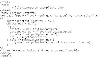


You'll see the following output when the adapter acquires the connection:

In MyManagedConnectionFactory.createConnectionFactory,1
In MyDataSource
In MyDataSource.getConnection,1
In MyManagedConnectionFactory.matchManagedConnections
In MyManagedConnectionFactory.createManagedConnection
In MyManagedConnection
In MyConnectionEventListener
In MyManagedConnection.getMetaData
In MyConnectionMetaData.constructor
In MyConnectionMetaData.getEISProductName
In MyConnectionMetaData.getEISProductVersion
In MyConnectionMetaData.getMaxConnections
In MyManagedConnection.getUserName
In MyManagedConnection.getConnection
In MyConnection
In MyManagedConnection.addMyConnection
In MyManagedConnection.addConnectionEventListener


If you are able to see the mentioned output, now you are ready to build your own connector.

Sunday, July 18, 2010

1.1 For SSL Communication Support (Integrating WebLogic Server with TIBCO EMS)

Note : Presuming we have integrated WebLogic Server with TIBCO EMS as described in the previous post.

Now as we have already configured MDB deployed on WebLogic Server to listen to JMS destination (in our example we configured Queue, it can be configured for Topic also in the same way), we will modify a bit to add SSL support. It can be done by following the simple steps:

Add the SSL JAR Files and New JNDI Properties File to the CLASSPATH

Add SSL JAR Files and New JNDI Properties File to the WebLogic Server CLASSPATH, by adding the following lines in front of the CLASSPATH variable value in startup script.

C:\tibco\ems\clients\java\jcert.jar;C:\tibco\ems\clients\java\jnet.jar;C:\tibco\ems\clients\java\jsse.jar;C:\tibco\ems\clients\java\tibcrypt.jar;C:\tibco\EMS\clients\java;

Create a new file named jndi.properties, add the following lines and save it to the directory C:\tibco\EMS\clients\java.

com.tibco.tibjms.naming.security_protocol=ssl
com.tibco.tibjms.naming.ssl_enable_verify_host=false

These properties specify that the "SSL" protocol should be used for JNDI lookups and that host verification is turned off (the client will trust any host). JNDI reads this file automatically and adds the properties to the environment of the initial JNDI context.

Configure the TIBCO Enterprise Message Service Server for SSL

In C:\tibco\EMS\bin\tibemsd.conf, add the following lines:

listen = ssl://localhost:7243
ssl_server_identity = certs/server.cert.pem
ssl_server_key = certs/server.key.pem
ssl_password = password
listen = tcp://localhost:7222

These lines explicitly set the tcp and ssl listen ports and specify the three required server-side SSL parameters identity, private key, and password.

Save the file, then stop and restart the TIBCO Enterprise Message Service server. When the server restarts, you should see messages like the following in the console window confirming SSL is enabled:

2010-07-18 10:00:05 Secure Socket Layer is enabled, using openSSL
2010-07-18 10:00:05 Accepting connections on ssl://:7243.
2010-07-18 10:00:05 Accepting connections on tcp://:7222.

Now modify the foreign JMSConnectionFactory in WebLogic to point to an SSLConnectionFactory

Open TIBCO_JMSServer properties from Services > Messaging > JMS Modules > MySystemModule > TIBCO_JMSServer of WebLogic Administration consoles and change the "JNDI Connection URL" to "tibjmsnaming://localhost:7243"

Modify the Example Client Program for SSL-Based Communication

In the "MyClient.java", change the value for "PROVIDER_URL" to "tibjmsnaming://localhost:7243"

We are now done with the modification for SSL support. To show that SSL communications are in fact occurring, you could remove the SSL settings you added to tibemsd.conf. Then restart the TIBCO Enterprise Message Service server and the WebLogic Server. If you check the WebLogic Server logs, you should see exceptions thrown indicating that it could not connect. If you now run the "MyClient.java" again, you should see that it throws an exception indicating that it could not connect to the server using the SSL protocol. Alternatively (or additionally), you could start the TIBCO Enterprise Message Service server from a command prompt window and turn SSL debug tracing on, as follows:

>tibemsd -ssl_debug_trace

Then, if you re-start WebLogic Server and re-run the test program, you will see SSL debugging output on the tibemsd console window.

Friday, July 9, 2010

1. Integrating WebLogic Server with TIBCO EMS

As we have been talking about integrating Application Servers and different messaging systems, lets take a tour to see how to use TIBCO Enterprise Message Service to drive a Message Driven Bean deployed in WebLogic Server.

(In case you are looking for an example MDB and client, please get it from HERE. Please compile it and create a deployable JAR).

Make the following configuration changes to the WebLogic Server and the example MDB to use TIBCO EMS instead of WLS JMS subsystem.

A> Add the TIBCO Enterprise Message Service JAR file to the CLASSPATH of WebLogic Server.

B> Create the appropriate foreign JMSConnectionFactory and foreign JMSDestination for the foreign JMS Server, TIBCO Enterprise Message Service, in WebLogic. This is necessary to allow the WebLogic server to redirect lookups of ConnectionFactory and Destinations in its JNDI to TIBCO Enterprise Message Service's JNDI.

C> Create the appropriate JMS Destination object inside the TIBCO EMS using its administration tool.

D> Modify the weblogic-ejb-jar.xml file for the MDB to use appropriate JMSConnectionFactory and JMSDestination.

E> Modify the client program to look up its administered objects from the built-in JNDI provider in TIBCO Enterprise Message Service.

A. Adding TIBCO Enterprise Message Service to the WebLogic CLASSPATH

Modify the CLASSPATH environment variable in WLS startup script by adding this path to the end of its value list:

C:\tibco\ems\clients\java\tibjms.jar (presuming you have installed TIBCO EMS in C:\tibco)

B. Creating Foreign JMSServer, JMSConnectionFactory, and JMSDestination in WebLogic

1> Start WebLogic Domain (Admin Server) and log in to Admin Console.

2> In the left pane, Create a Foreign Server under:
Services > Messaging > JMS Modules > MySystemModule > New > Foreign Server (my already created JMS Module name is "MySystemModule")

Enter TIBCO_JMSServer in the Name box, after creating, go to the Foreign Server and provide JNDI Initial Context Factory = com.tibco.tibjms.naming.TibjmsInitialContextFactory
JNDI Connection URL = tibjmsnaming://localhost:7222

Go to Connection Factories tab and create a new Connection Factory:
Name = TIBCO_JMSQueueConnectionFactory
Local JNDI Name = TIBCO.tcf
Remote JNDI Name = QueueConnectionFactory

Go to Destinations tab and create a new Destination:
Name = TIBCO_JMSQueue_quotes
Local JNDI Name = TIBCO.quotes
Remote JNDI Name = quotes

C. Creating appropriate JMS Destination object inside the TIBCO EMS

1> Start the TIBCO Enterprise Message Service server by selecting Start -> Programs -> TIBCO Enterprise Message Service -> Start JMS Server from the Windows Start menu.

2> Start the TIBCO Enterprise Message Service administration tool by selecting Start -> Programs -> TIBCO Enterprise Message Service -> Start EMS Administration Tool from the Windows Start menu.

3> Enter the following commands:
> connect
> create topic quotes

D. Modifying the weblogic-ejb-jar.xml file for MDB

To use the appropriate JMSConnectionFactory and JMSDestination modify weblogic-ejb-jar.xml as follows:

1> Replace the value for element with TIBCO.quotes.

2> Within the element and immediately after both instances of the element, add the following element:


E. Modify the Client

1. change the following:
QUEUE_NAME = "quotes";
CONNECTION_FACTORY = "QueueConnectionFactory";
PROVIDER_URL = "tibjmsnaming://localhost:7222";
java.naming.factory.initial = com.tibco.tibjms.naming.TibjmsInitialContextFactory

2. Verify that you have tibjms.jar in classpath.

Now everything is set, so deploy the MDB in WLS and test the client. If you can see your client program is sending messages and the MDB in WLS is consuming them and printing the o/p in WLS server startup prompt then we have successfully configured MDB deployed in WebLogic to listen to TIBCO EMS destination where messages are delivered by a standalone client.

Thursday, May 13, 2010

Integrating WebLogic Server with Websphere MQ

Most of the production system configuration relies on messaging now-a-days and which requires compatibilities and interconnection between different middleware servers and messaging system e.g. WebLogic and WebSphere MQ JMS.

In the following steps I tried to make it simple and clear. Depending on the business need it can be re-scaled or re-architect.

Links might help:
1> WebSphere MQ System Requirement
2> WebLogic System Requirement (I will be using WLS8.1 SP4 instance on Windows)

Creating WebSphere MQ queue manager and configuring JMS JNDI namespace

To work with this example, you need to have a QueueConnectionFactory and Queue objects created in JNDI namespace to connect to the queue manager and access queues. Use the following commands to create a queue manager and queues in WebSphere MQ:

1. Create the queue manager: crtmqm testqmgr.
2. Start the queue manager: strmqm testqmgr.
3. Create queues in the queue manager:

runmqsc testqmgr
DEFINE QLOCAL("MyMDBQueue")
DEFINE QLOCAL("MyReplyQueue")
end

Next, create a simple file-based JNDI context and configure the JMS objects in that JNDI namespace. These JNDI objects are used by applications running in WebSphere Application Server Community Edition to connect to the WebSphere MQ queue manager. For this exercise, WebLogic and WebSphere MQ should be on the same machine.

The setting is for file-based JNDI. Create the directory C:\JNDI-Directory before continuing with the next step. Create MyAdmin.config with the following contents:

INITIAL_CONTEXT_FACTORY=com.sun.jndi.fscontext.RefFSContextFactory
PROVIDER_URL=file:/C:/JNDI-Directory
SECURITY_AUTHENTICATION=none

Next, create the QueueConnectionFactory and Queue objects by executing the command:

C:\Program Files\IBM\WebSphere MQ\Java\bin\JMSAdmin.bat -cfg MyAdmin.config

You should see this prompt, where you can configure the JNDI objects: InitCtx>

At the prompt, type the following commands and press Enter after each one:

def xaqcf(ReceiverQCF) qmgr(testqmgr)
def xaqcf(SenderQCF) qmgr(testqmgr)
def q(MyMDBQueue) qmgr(testqmgr) queue(MyMDBQueue)
def q(MyReplyQueue) qmgr(testqmgr) queue(MyReplyQueue)
end

The above configurations are basic steps. For more information about the JMSAdmin tool, CLICK HERE (search for "Using the WebSphere MQ JMS administration tool")

Creating a WebLogic server instance

Create a WebLogic server instance, then add the WebSphere MQ JMS JAR files to its classpath and do the configuration steps below:

1. Install WebLogic Server, for example in C:\bea.
2. Open a command window (cmd.exe).
3. Execute C:\bea\weblogic81\server\bin\setWLSEnv.cmd.
4. Create the server by using the wizard: Click
Start => All Programs => BEA WebLogic Platform 8.1 => Configuration Wizard

Or you can use the following command:
1. Create a directory where you want to run the test, such as C:\jms\WebLogic\test\server, and make it your current directory.
2. Execute the following command to create the domain and server:

java -Dweblogic.Domain=MQJMSTEST -Dweblogic.Name=MQJMSTESTSERVER
-Dweblogic.management.username=weblogic -Dweblogic.management.password=weblogic
-Dweblogic.management.GenerateDefaultConfig=true weblogic.Server

5. After the above command has completed, stop the server, open another command window, and call C:\bea\weblogic81\server\bin\setWLSEnv.cmd by executing the following command:

java weblogic.Admin -url t3://localhost:7001 -username weblogic
-password weblogic FORCESHUTDOWN

6. Configure the WebLogic Server classpath to access the WebSphere MQ JMS JAR files by editing C:\jms\WebLogic\test\server\startMQJMSTEST.cmd and adding the following line just before the last command to start the server JVM:

set MQ_JAVA=C:\Program Files\IBM\WebSphere MQ\Java\lib
set CLASSPATH=%MQ_JAVA%\com.ibm.mq.jar;%CLASSPATH%
set CLASSPATH=%MQ_JAVA%\com.ibm.mqjms.jar;%CLASSPATH%;
set CLASSPATH=%MQ_JAVA%\com.ibm.mqetclient.jar;%CLASSPATH%
(Above line is applicable only for WebSphere MQ + Extended Transactional Client)
set CLASSPATH=%MQ_JAVA%\fscontext.jar;%CLASSPATH%
set PATH=%MQ_JAVA%;%PATH%

7. Start the server by executing C:\jms\WebLogic\test\server\startMQJMSTEST.cmd.

WebLogic Server should be running. Access its admin console using http://localhost:7001/console and authenticating with user name and password (in this example we used weblogic for both).

Configuring a WebLogic foreign JMS server

Next, configure the WebLogic foreign JMS provider with the JNDI setting to access it.

Access http://localhost:7001/console, authenticating with the user name and password used in creating the WebLogic server instance above. After login, navigate to MQJMSTEST => Services => JMS => Foreign JMS Servers. In the right pane, click Configure a new Foreign JMSServer and enter the following values:

* Name: MQJMSTEST Foreign JMS Server
* JNDI Initial Context Factory: com.sun.jndi.fscontext.RefFSContextFactory
* JNDI Connection URL: file:/C:/JNDI-Directory

The screen should look like this:


Figure 1. Creating new Foreign JMS Server.

Click Create at right bottom. You will get another screen to choose the instance of WebLogic Server where this foreign JMS server needs to be created. Select MQJMSTESTSERVER and click Apply.

Now you are ready to configure the QueueConnectionFactory and Queue objects in the newly created foreign JMS provider. By this step what we will be doing is that referring the QueueConnectionFactory and Queues defined in the file-based JNDI as a foreign JMS provider.

Creating QueueConnectionFactory objects in a foreign JMS provider

Navigate to MQJMSTEST => Services => JMS => Foreign JMS Servers => MQJMSTEST Foreign JMS Server => Foreign JMS Connection Factories. In the right pane, click Configure a new Foreign JMSConnection Factory and enter the following values:

* Name: WLSenderQCF
* Local JNDI Name: jms/WLSenderQCF
* Remote JNDI Name: SenderQCF

The remote JNDI Name should match the QueueConnectionFactory name created in the file-based JNDI using the JMSAdmin tool. The screen should look like this:


Figure 2. Creating QueueConnectionFactory.

Click Create at right bottom to complete this operation.

Creating destination objects in the foreign JMS provider

To create the destinations, navigate to MQJMSTEST => Services => JMS => Foreign JMS Servers => MQJMSTEST Foreign JMS Server => Foreign JMS Destinations. In the right pane, click Configure a new foreign JMSDestination and enter the following values:

* Name: WLMyReplyQueue
* Local JNDI Name: jms/WLMyReplyQueue
* Remote JNDI Name: MyReplyQueue

The remote JNDI Name should match the destinations created in the file-based JNDI using the JMSAdmin tool. The screen should look like this:


Figure 3. Creating Queue Destination.
Creating Queue Destination

Click Create at right bottom to complete the operation. Now you are ready with foreign JMS configurations to look into the MDB application.

Developing a sample application and deploying it on WebLogic

Here we use an MDB that is listening for the messages from MyMDBQueue in Queue manager testqmgr. The onMessage() picks up the messages and forwards the same message to MyReplyQueue by calling the putMessage(javax.jms.Message msg) method.

A sample application can be downloaded from HERE

1. Open a command prompt and execute the following commands:

2. cd C:\wlresources

3. C:\bea\weblogic81\server\bin\setWLSEnv.cmd

4. javac com\ibm\WLSampleMDB\SampleMDBBean.java

5. jar -cvf WLSampleMDB.jar com META-INF (creates WLSampleMDB.jar, on which you will work further to deploy it on the server ).

6. Start the Application Builder: Click Start => All Programs => BEA WebLogic Platform 8.1 => Other Development Tools => WebLogic Builder.

7. In WebLogic Builder, click File =>Open and select the WLSampleMDB.jar created in Step 5 (if prompted, click Yes for creating the Deployment Descriptors).

8. Click SampleMDBBean on the left-side tree view, select the General tab, and change the following values:

* JNDI Name: SampleMDBBean
* Transaction Timeout: 300
* Destination Type: javax.jms.Queue
* Destination JNDI: MyMDBQueue (This is the name you have given when you created a queue using JMSAdmin tool)

9. Select the Foreign JMS Provider tab, select Use Foreign JMS Provider, and enter the following values:

* Provider URL: file:/C:/JNDI-Directory
* Connection Factory JNDI Name: ReceiverQCF (The Connection Factory name we created using the JMSAdmin tool for the MDB to receive the messages)
* Initial Context Factory: com.sun.jndi.fscontext.RefFSContextFactory

10. Select the Advanced tab and ensure that for Transaction Type, the value Container is selected.

11. From the left-side tree view, under SampleMDBBean, select Methods and ensure that Default transaction is selected as required.

12. From the left-side tree view, under SampleMDBBean, select Resources.

13. Select the Resource Reference tab from the right-side pane and click Add (if the resources are already defined, click Edit). Enter the following values:

* Resource reference Name: WLSenderQCF
* Resource Type: javax.jms.QueueConnectionFactory
* Resource Authority: Application
* JNDI Name: jms/WLSenderQCF
* Sharing Scope: Unsharable

14. Click OK. Similarly add another resource reference with following values:

* Resource reference Name: MyReplyQueue
* Resource Type: javax.jms.Queue
* Resource Authority: Application
* JNDI Name: jms/MyReplyQueue
* Sharing Scope: Unsharable

15. Click File => Save to save Save WLSampleMDB.jar.

16. To deploy this assembled JAR file, click Tools => Deploy Module. If you are asked for the configuration values to connect to WebLogic Server, verify that they match the values below:

* Protocol: t3
* Host: localhost
* Port: 7001
* Server Name: MQJMSTESTSERVER
* System User Name: weblogic
* System User Password: weblogic
* Now click Connect and in next pop-up window, click Deploy Module.

17. Test the application using the command amqsput MyMDBQueue testqmgr from the command prompt and type any text you want to put it as a message, now observe the console where the WebLogic Server is running and you should be able to see something like this:

Message Received:
JMS Message class: jms_text
JMSType: null
JMSDeliveryMode: 1
JMSExpiration: 0
JMSPriority: 0
JMSMessageID: ID:414d512074657374716d6772202020203f40254420000908
JMSTimestamp: 1143559825190
JMSCorrelationID:null
JMSDestination: null
JMSReplyTo: null
JMSRedelivered: false
JMS_IBM_PutDate:20060328
JMSXAppID:WebSphere MQ\bin\amqsput.exe
JMS_IBM_Format:MQSTR
JMS_IBM_PutApplType:11
JMS_IBM_MsgType:8
JMSXUserID:sanjay
JMS_IBM_PutTime:15302519
JMSXDeliveryCount:1
This is a Test Message

putting the message to MyReplyQueue
looked up QueueConnectionFactory: weblogic.deployment.jms.PooledConnectionFactory@8710bd
looked up Queue: queue://testqmgr/MyReplyQueue
Message send

If you see the above mentioned line properly, then we have configured WebLogic Server and WebSphere MQ to connect to each other and used an MDB sample to get a message and forward it to another queue within a global transaction.

Cloud vs. Cloud Native

Introduction These days everyone is moving “On cloud”. Having many cloud vendors with lucrative offers of TCO reduction, does deploying yo...